
Phase One & Mamiya AF Pinout

For awhile now I have wanted to reverse engineer the Mamiya & Phase One lens interface, with the goal of being able to control the apertures of any Mamiya AF, Phase One, or Schneider Kreuznach lens. Mamiya originally developed this lens interface for their 645AF camera back in 1999, and Phase One/Mamiya extended it with the Phase One XF by adding a new row of 6 pins below the existing 8 pin interface.

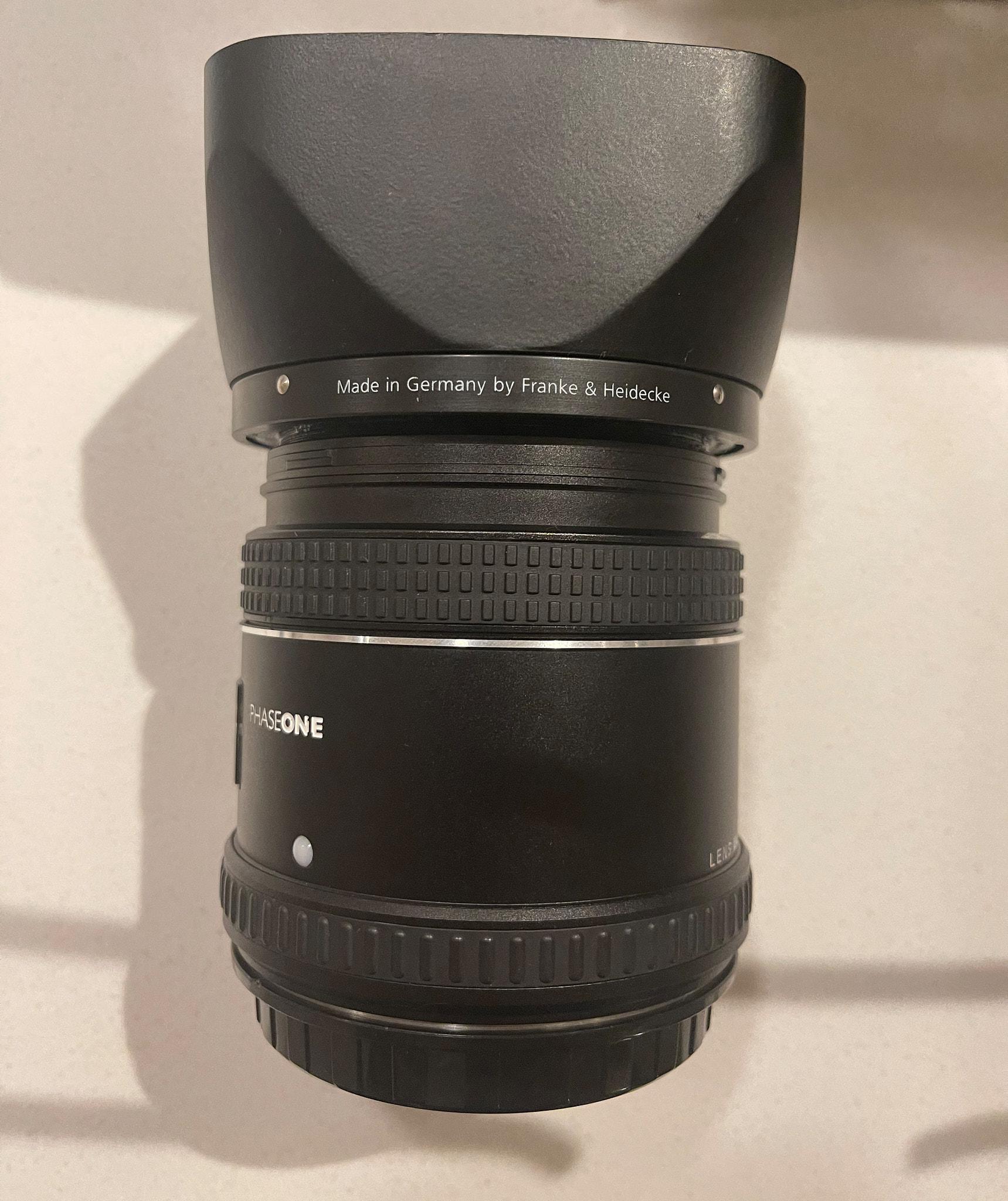
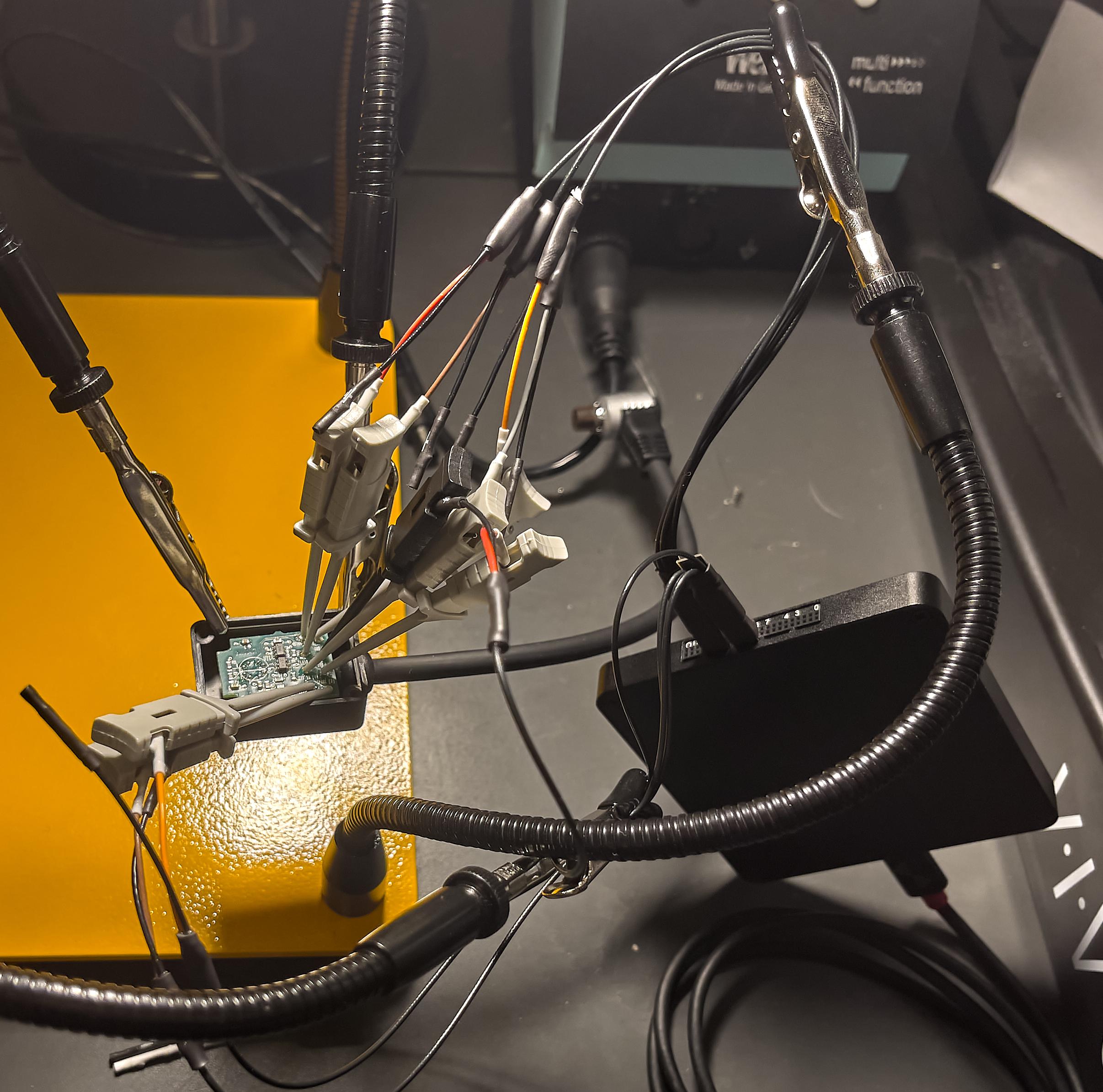
By using the rings from a Mamiya 645AF Macro Bellows with a minor modification, I was able to connect a 80mm lens to my 645AFD and Phase One XF remotely. This let me gain access to the lens interface while still having a lens connected, which is critical because the interface does nothing unless it detects a lens is mounted.

/images/phaseone07.jpg/images/phaseone08.jpg

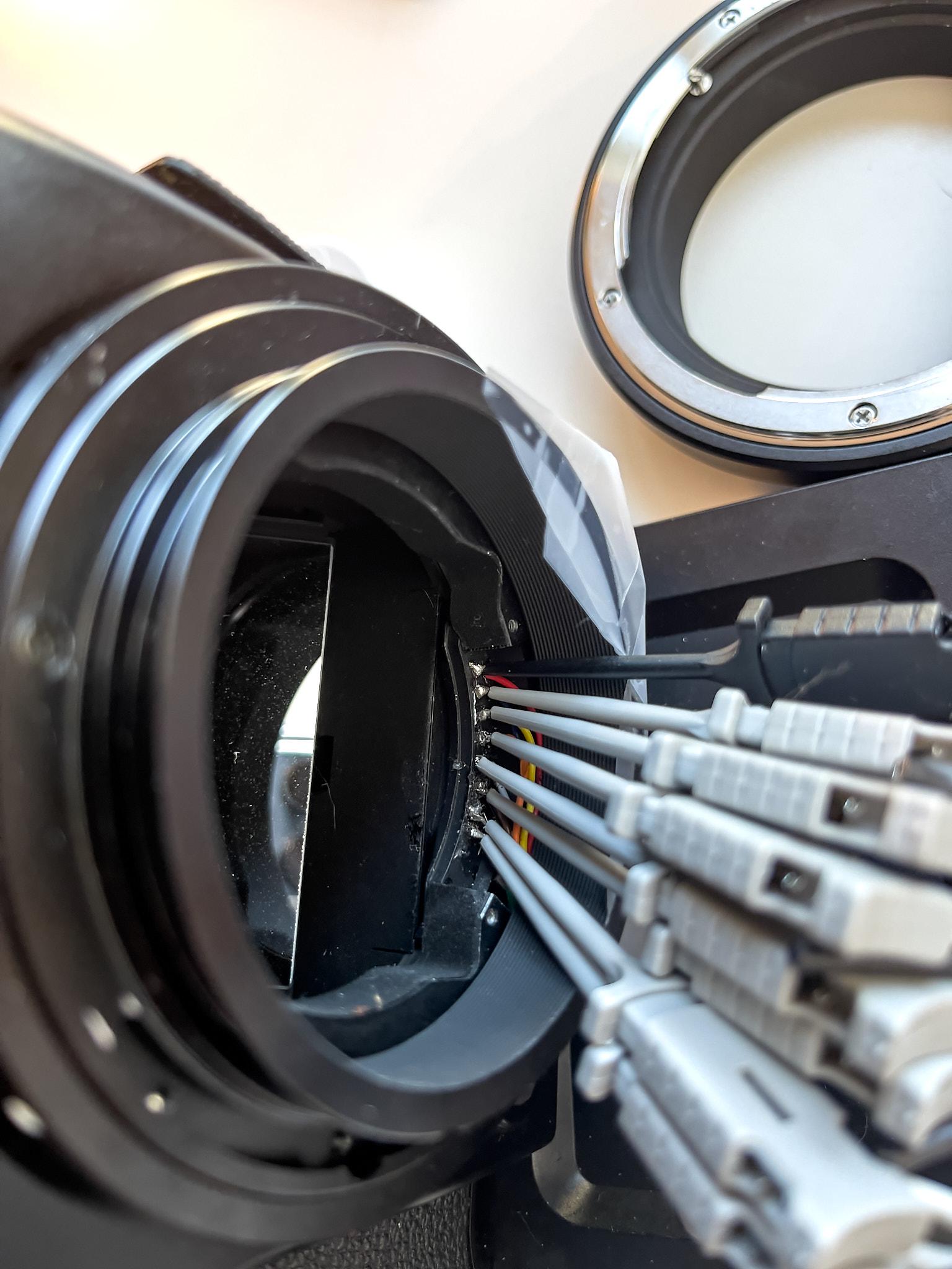
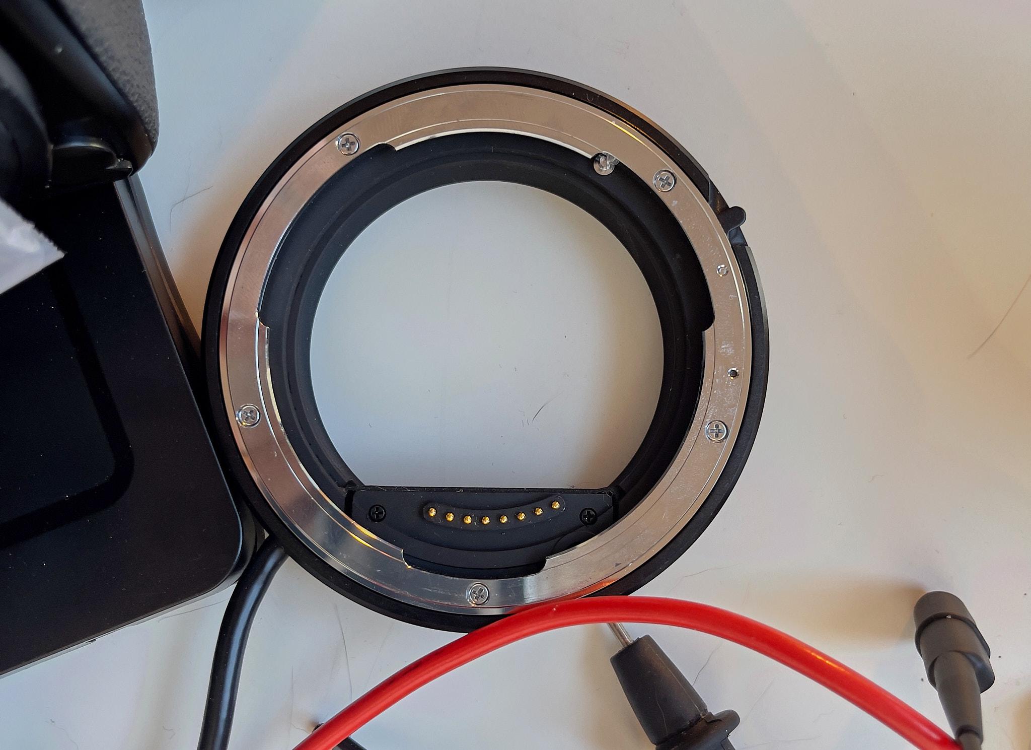
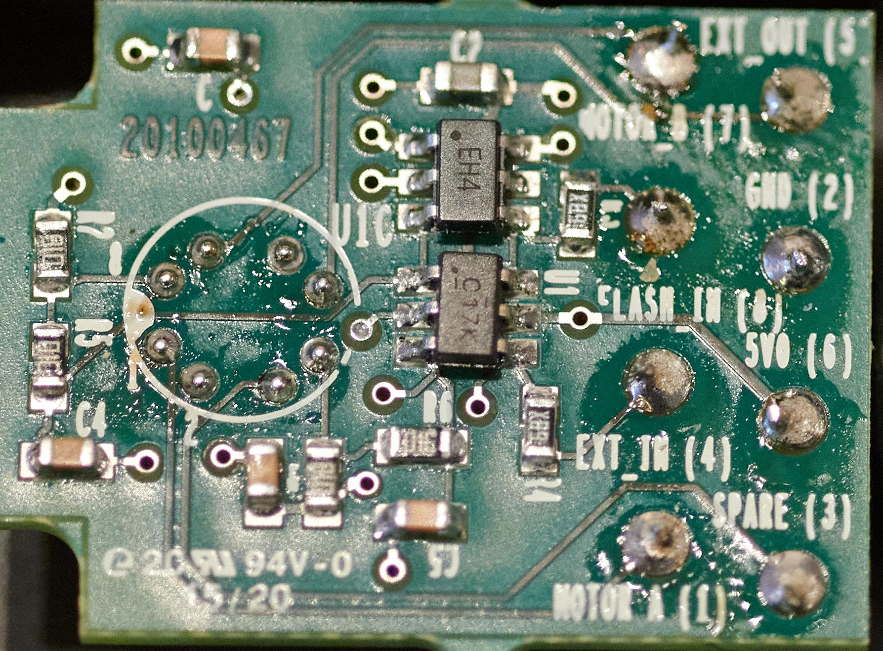
The first step was to figure out the ground, which I did by guessing that the GND and main voltage would probably be as far apart from each other as possible, and that the main voltage source would be the last contact to interface when rotating the lens into position on the mount. This actually turned out to be a great guess, as the first pin to the right looking at the camera body front is GND, and the first contact that every pin will slide over as the lens is rotated. The pin to far left, pin 6 in my labeling, was 8.89 volts, which is probably the unregulated output of the 6AA batteries in the 645AFD I was using when taking voltage measurements. On the XF this is probably 7.2v or whatever the BP915 battery back is putting out. The next pin over, pin 5, measured 5.12V, which is probably the regulated logic voltage. The rest of the pins operate at a 5V logic level at least. Pin 4 is either a sense pin of some kind, for leaf shutter lenses, or not used - it does seem to pulse to a ~1V on camera power on, but otherwise does nothing. The rest of the pins are part of the serial interface.

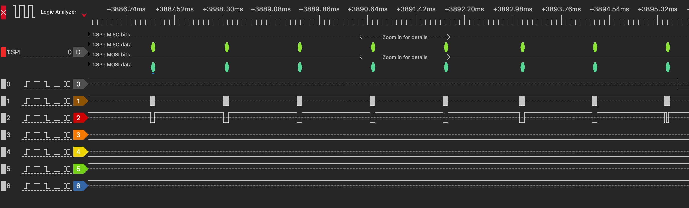
After hooking up my logic analyzer, it appeared there was a 100Khz clock sometimes on Pin 1: .. image /images/mamiya_afd_speed.png This was true for both the Mamiya AFD and the Phase One XF I tested. There was also what looked data on Pin 2 and Pin 3, looking at Pin 0, it was always 1 when data was being transferred, and toggled low at the end of a sequence of transfers. I figured that this was likely basically standard SPI, and guessed that Pin 2 was MOSI and Pin 3 was MISO purely because Pin 2 always sent data first before Pin 3 responded. After setting up the SPI decoder for the corresponding pins, it seems like I was successful, and SPI data that looks a lot like the Digital back protocol is being captured :)

/images/XF_PROTOCOL_SNIPPET.png

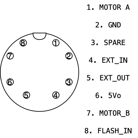
The final pinout, as I have been able to determine:

/images/phaseone05.jpg

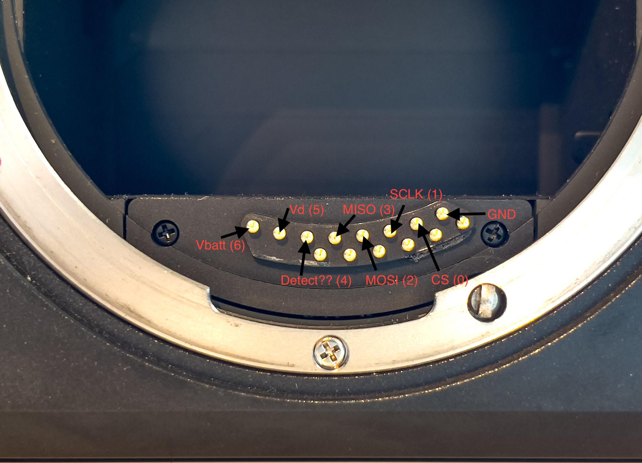
I don't have any of the newest (and very expensive!) Blue Ring lenses to determine what the newer row of 6 pins does, but with the top 8 pins understood simple aperture control should be possible with any 645AF lens; once I can reverse the protocol for controlling the lens. So far, it looks very similar to the Digital Back Protocol that has already been reverse engineered by others for the older pre XF cameras (645DF/AFDIII/AFDII/AFD) here

3D Printed Rollei Bayonet VI to 67mm Filter Thread Lens Hood

Once upon a time I owned a Leaf AFi and several lenses - now long sold for more practical things. I however did accidentally hang onto one lens hood. I hate most lens hoods, as they are often cheap plastic that looks terrible, and on older lens, needs to be screwed into the filter threads sometimes. I figured instead of selling the hood on ebay, I'd print a adapter from 67mm filter thread to the Rollei Bayonet VI mount that Rollei used on many of their PQ lenses for the HY6 system. Here's the finished product:

/images/phaseone06.jpg

A screencap of the STL from preview:

/images/rollei67mm.png

You can download a few different sizes of the adapter here:

62mm 67mm 72mm

Datahoarding and ML Server Build

My home server is a little bit silly. It's certainly not as over the top as some builds on the DataHoarder subreddit, but I think it's a neat little build. It's evolved a lot over the years, and I've tried to document a bit of it hear so other people can get ideas from it.

Hardware

As a side effect of a past job at Silicon Mechanics, I gained a not so minor affection for real sever grade hardware. No core i7's or Ryzen's here, instead we have the following hardware:

/images/ultra2.png

Motherboard

Supermicro X11-SPM-F

CPU

Intel Xeon Gold 5217 8 cores @2.8GHz

RAM

4x 16GB Samsung 2133MHz ECC RDIMM

RAM

2x 128GB Intel 2666MHz ECC DCPMM

GPU

Nvidia Tesla M40 24GB :D

HBA

LSI SAS3008 SAS3

Boot SSD

Samsung SSD 950 PRO 512GB

Storage SSD

Fusion ioScale 3.20TB MLC SSD

HDD

2x 12TB ZFS Mirrors, 1x6TB ZFS Mirror

Case

Phanteks Eclipse P600S

Overall it's a pretty decent system for everything I ask of it! I've had no issue other than a RAM stick going bad, which was quickly caught by ECC and noted in the IPMI interface of the X11 board. While Supermicro motherboards may be basic, they are rarely buggy in ways that are showstoppers. This is very different than my personal experience with Asrock, EVGA, or gigabyte boards I've used in various systems that all had weird issues that would appear after running them for long periods, or just randomly. Also, I really really like not having to plug in a monitor and keyboard to interface with the system, including for power/reset. Though these days there is now Pi-KVM at least in place of a real IPMI.

GPU

The M40 GPU took some work to cool down properly, and in some training runs it still starts to throttle down. The GPU came from eBay (as did most of the parts of this system) without a fan, and orignally I printed out this model from Thingiverse. It actually worked really well, but was too unbearably loud. I was unhappy with the other models I could find online, so I designed my own 3D simple fan attachment funnel:

/images/m40.png

It's also not the fastest deep learning card out there by a long shot, but I wanted to research more into transformer models, and it was by far the cheapest way to get 24GB of VRAM - I paid ~200 for mine! Performance wise, It achieves about 4300GFLOPS in the gpu-burn testing application I like using. In terms of deep learning performance, using the data from Lambada Labs to compare, the M40 is XX% slower running the transformerxlbase model.

Memory

The memory setup on my system is a bit different than most. The memory on my sever is split between 64GB of standard error correcting registered memory, typical for servers, and 256GB of Optane flash memory in two DIMM slots. Optane is a pretty cool technology - unlike current consumer SSDs, Optane works really well at low queue depths, the number of outstanding operations. Normal SSDs that use even single level flash have to queue many operations in parallel to achieve good performance, Optane is able to get great performance (fast and low latency) with just one operation.

What this enabled beyond really awesome SSDs is the Datacenter persistent memory module, or DCPMM. Intel developed the DCPMM which puts Optane flash modules and a controller on the DDR4 bus as either bulk memory for the computer, or in several direct access modes. Unfortunately Optane seems to be a consumer failure though, as Intel has canceled all future consumer targeted Optane products. It was a very inexpensive way to transparently get a lot of performance from ZFS by having lots of RAM, without spending a lot of money.

FusionIO SSD

All the other hardware is pretty standard and boring, though the bulk storage SSD is somewhat interesting - it's an old FusionIO SSD that uses a FPGA and a bunch of flash chips to implement a very fast SSD, even considering available SSDs now. For example, it gets up to 345K/385K IOPS R/W. It doesn't slow down much as it fills past 90%, unlike modern SSDs, and uses MLC, not TLC, which gives it much more well-rounded performance in tail-end scenarios. Note these are note NVME and getting them working in Ubuntu 20.04 requires using this driver.

Software

Section Coming in the Future!

What Does it Do?

I use the server in many different ways:

  • It runs a NFS fileserver serving my laptop and desktop with bulk storage

  • Manages my condo's wireless lights and switches via the excellent homebridge project

Phase One 8 Pin Sync Cable Pinout

For many (literally) years, I've been looking for any information on the pinouts/connectors for old Phase One and Mamiya gear. The main reason for doing so is to make developing custom camera bodies for digital backs.

It turns out that the Phase One Sync Cleaner Cable has a pinout silkscreened onto the board!

/images/syncCleaner_05.jpg

The pinout of the connector: 1. MOTOR A 2. GND 3. SPARE 4. EXT_IN 5. EXT_OUT 6. 5Vo 7. MOTOR_B 8. FLASH_IN

And a helpful image diagram, looking at the connector top down:

/images/sync.png

I'm still searching for the name of this connector, but at least now we know what it connects to! Next up is to throw it under the logic analyzer:

/images/syncCleaner_06.jpg

I'm using an inexpensive dslogic plus USB logic analyzer (LA), which is simple to use. Each channel has a pair of flying leads, one to tap the signal under test and the other a ground. While each wire has a ground, this LA has a common ground for everything (Including the USB port!).

After setting everything up, I plugged the sync cleaner cable into the 8 pin port on my digital back, and hooked the dslogic plus up to my MacBook. When I triggered the back's electronic shutter every signal recorded a logic low except the EXT_IN and FLASH_IN signals, which were pulled high. That at least, makes sense, as in theory you should be able to trigger this back by pulling either input low. Perhaps my back has a broken 8 pin connector (very unlikely), or I'm using the LA wrong (more likely), or more interesting things only happen when connected to a body. I also tried capturing any signals that occurred when the back powered up/down, but this also didn't show anything useful, other than the signals that are typically pulled high getting pulled low.

While somewhat disappointing that I couldn't see anything with my LA, at least there are other ways to control the back without using a body, if I can find/manufacture a connector to the interface between the body and the back. Hopefully probing the lens interface to understand how to manually control the lens apertures for the Mamiya/Phase One 645 mount is more enlightening :)